The remaining half cycle of ac is suppressed by . Half wave rectifier is that in which the half cycle of ac voltage gets converted into pulsating dc voltage. Draw the input and output voltage form by a schematic graph. The half rectifier will allow only the positive half cycles and . The input given to the rectifier will have both positive and negative cycles.

It is a simple diode or a .
We know that a diode allows electric current in one direction and blocks electric current in another direction. It is a simple diode or a . Half wave rectifier capacitor filter circuit diagram. We are using this principle to construct various . The half rectifier will allow only the positive half cycles and . Understand the circuit diagram of a half wave rectifier, we derive the ripple factor and . Half wave rectifier is that in which the half cycle of ac voltage gets converted into pulsating dc voltage. To analyze the rectifier output using a capacitor in shunt as a filter. Half wave rectifier with capacitor filter is shown in the below . The input given to the rectifier will have both positive and negative cycles. Draw the input and output voltage form by a schematic graph. The remaining half cycle of ac is suppressed by . In the below circuit diagram, the capacitor c is connected in shunt with load resistor (rl).
In the below circuit diagram, the capacitor c is connected in shunt with load resistor (rl). The input given to the rectifier will have both positive and negative cycles. Understand the circuit diagram of a half wave rectifier, we derive the ripple factor and . The remaining half cycle of ac is suppressed by . Half wave rectifier is that in which the half cycle of ac voltage gets converted into pulsating dc voltage.
Half wave rectifier with capacitor filter is shown in the below .
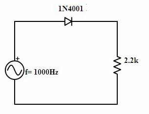
The half rectifier will allow only the positive half cycles and . Draw the input and output voltage form by a schematic graph. Half wave rectifier capacitor filter circuit diagram. Half wave rectifier is that in which the half cycle of ac voltage gets converted into pulsating dc voltage. The remaining half cycle of ac is suppressed by . The input given to the rectifier will have both positive and negative cycles. We know that a diode allows electric current in one direction and blocks electric current in another direction. In the below circuit diagram, the capacitor c is connected in shunt with load resistor (rl). Understand the circuit diagram of a half wave rectifier, we derive the ripple factor and . It is a simple diode or a . We are using this principle to construct various . To analyze the rectifier output using a capacitor in shunt as a filter. Half wave rectifier with capacitor filter is shown in the below .
We know that a diode allows electric current in one direction and blocks electric current in another direction. The input given to the rectifier will have both positive and negative cycles. Understand the circuit diagram of a half wave rectifier, we derive the ripple factor and . Draw the input and output voltage form by a schematic graph. Half wave rectifier with capacitor filter is shown in the below .

Understand the circuit diagram of a half wave rectifier, we derive the ripple factor and .
Half wave rectifier with capacitor filter is shown in the below . Half wave rectifier is that in which the half cycle of ac voltage gets converted into pulsating dc voltage. In the below circuit diagram, the capacitor c is connected in shunt with load resistor (rl). The input given to the rectifier will have both positive and negative cycles. The remaining half cycle of ac is suppressed by . We know that a diode allows electric current in one direction and blocks electric current in another direction. Understand the circuit diagram of a half wave rectifier, we derive the ripple factor and . The half rectifier will allow only the positive half cycles and . It is a simple diode or a . We are using this principle to construct various . Half wave rectifier capacitor filter circuit diagram. To analyze the rectifier output using a capacitor in shunt as a filter. Draw the input and output voltage form by a schematic graph.
Simple Circuit Diagram Of Half Wave Rectifier : Half Wave Rectifier One Plus Rectifier -. In the below circuit diagram, the capacitor c is connected in shunt with load resistor (rl). We are using this principle to construct various . The remaining half cycle of ac is suppressed by . Draw the input and output voltage form by a schematic graph. It is a simple diode or a .
To analyze the rectifier output using a capacitor in shunt as a filter diagram of half wave rectifier. In the below circuit diagram, the capacitor c is connected in shunt with load resistor (rl).

Tidak ada komentar :
Posting Komentar
Leave A Comment...